How to connect a reversing switch to a 3- or 4-wire (psc) gearmotor Circuit reset diagram system seekic basic below Atmega32 atmel avr microcontroller
8051 Reset Circuit Diagram
Using push button switch with atmega32 microcontroller atmel studio Bersa reversing switch wiring diagram Reset 8051 circuit power
Switch in a circuit diagram
Phase contactor wiring diagram motor switch reverse forward wire stop contact startSingle phase motor reverse forward wiring connection @mianelectric Power on reset circuit schematicThe reset system circuit diagram.
Figure 2: block diagram of the reset switch8051 reset circuit diagram Power supply8051 power on reset circuit(हिन्दी ).

Automatic transfer switch ats circuit diagram
Simplified block diagram of on-chip reset circuitAutomatic changeover switch circuit diagram Reset circuit 8051 microcontroller low button connecting chip first stack electrical press enable pullsPolarity reversal using a dpdt switch.
Reversing motor wiring diagramHow to connect a reversing switch to a 3- or 4-wire (psc) gearmotor Rwandatechnician.com: 8051 microcontrollerWiring outlet fault slater ground puller gfci reset.

Reset switch diagram hardware block figure
Relay latching circuit using push button instrumentation tools3 phase motor contactor wiring diagram 6-circuit transfer switch wiring diagramButton reset circuit diagram.
How to program a switch for manual reset – dwyer instruments blogReversing switch motor dc diagram wiring polarity reverse dpdt ac circuit electric rollertrol switches wire simple drill 12v arduino device Dc motor control circuit diagram forward reverseSingle phase induction motor forward reverse connection diagram.
8051 reset circuit diagram
Reset switch circuit diagramWiring diagrams 6 pin rocker switch wiring diagram » wiring digital and schematicHow to connect a reversing switch to a 3- or 4-wire (psc) gearmotor.
Automatic transfer switch circuit diagramCircuit diagram reset button seekic amplifier shown figure Reset chip simplified ic 29thRelay circuit button push using reset latching diagram hooter plc acknowledge signal hold command realy instrumentationtools replace shown note above.

Reset circuit 8051 microcontroller low button connecting chip first stack electrical press
.
.


8051 Reset Circuit Diagram
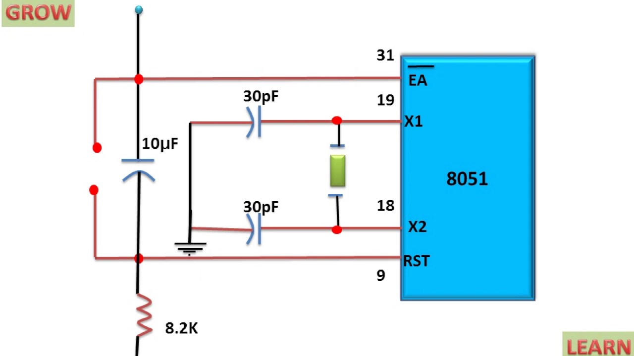
8051 Power On Reset Circuit(हिन्दी ) - YouTube

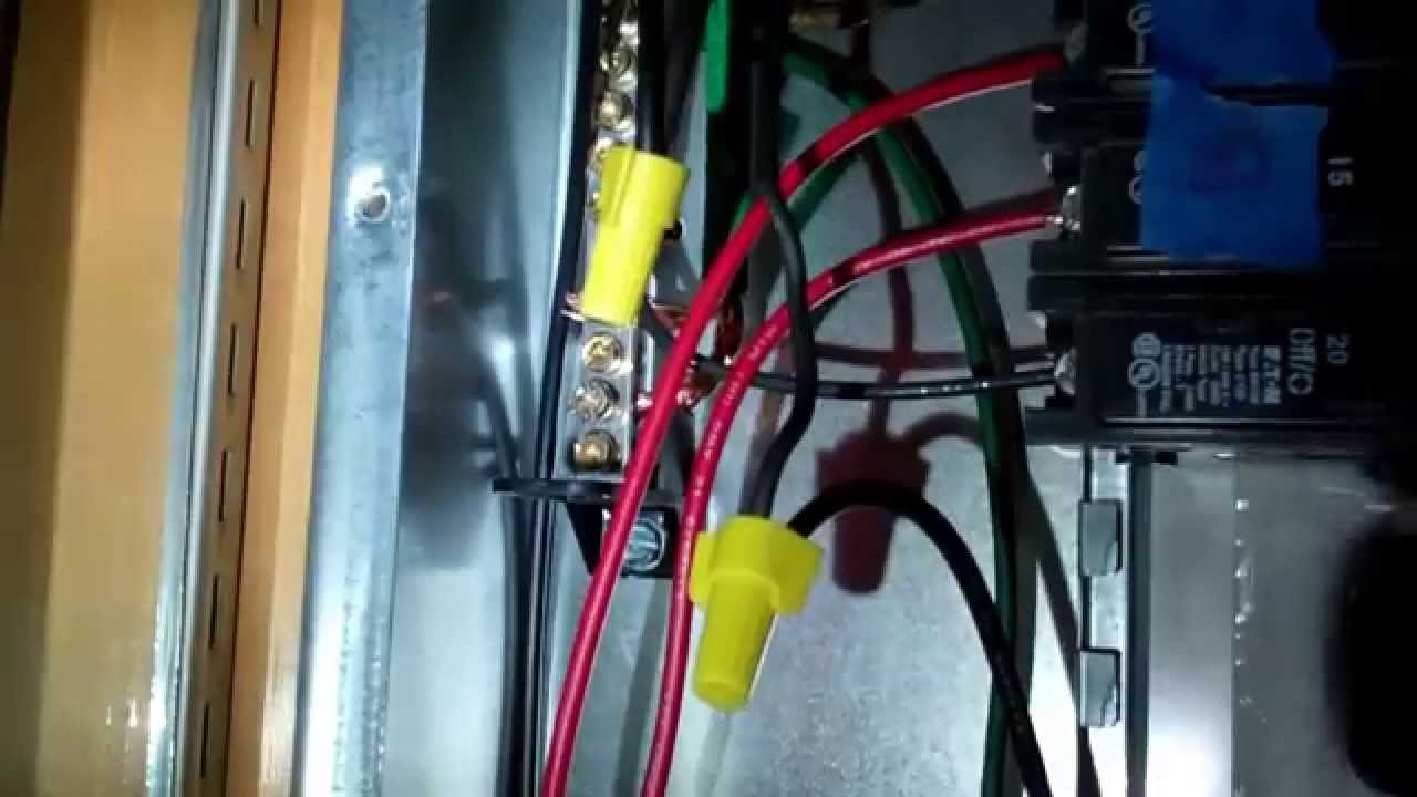
switches - Switch that resets when power is lost? - Electrical

How to Program a Switch for Manual Reset – Dwyer Instruments Blog

How To Connect a Reversing Switch to a 3- or 4-Wire (PSC) Gearmotor

Wiring Diagrams - Safe-T-Puller.comSafe-T-Puller.com

How To Connect a Reversing Switch to a 3- or 4-Wire (PSC) Gearmotor
